简述
回顾上一篇章中的读取图像的步骤:
- 首先利用stb-image库读取图片,将其内容存储在临时缓存区VkBuffer中,注意需要开辟GPU可见内存
- 通过VkImageCreateInfo结构指明图像格式并通过vkCreateImage创建VkImage对象
- 用VkBuffer图像文件中的像素填充创建的VkImage图像对象
- 填充图像对象需要使用VkImageMemoryBarrier
- 使用vkCmdPipelineBarrier使得图像填充Barrier生效
- 通过vkCmdCopyBufferToImage完成图像像素从VkBuffer到VkImage的拷贝(填充)
- 再通过VkImageMemoryBarrier指定图像是能够从着色器中的纹理图像开始采样
- 创建图像视图和图像采样器
- 添加一个组合的图像采样器描述符来从纹理中采样颜色
在图像采样器创建之前,我们首先看看纹理图像视图,这个是在我们创建交换链的时候见过:
一. 纹理图像视图 Texture Image View
通过VkImageView类来存储纹理图像视图, 它描述了如何访问图像以及要访问的图像部分,创建VkImageView的方式也是通过一个结构体:VkImageViewCreateInfo, 来指明细节. 这部分我们在之前的交换链创建图像视图中有过接触,如果忘记了的话可以回顾一下。
1
2
3
4
5
6
7
8
9
10
11
12
13
14
15
16
17
18
19
20
21
22
23
24
25
26
27
28
29
30
31
32
33
34
35
36
37
38
39
40
41
42
43
44
45
46
47
48
49
50
51
52
53
54
55
56
57
58
59
60
61
| VkImageView textureImageView;
void initVulkan() {
...
createTextureImage();
createTextureImageView();
createVertexBuffer();
...
}
VkImageView createImageView(VkImage image, VkFormat format) {
VkImageView imageView;
VkImageViewCreateInfo viewInfo = {};
viewInfo.sType = VK_STRUCTURE_TYPE_IMAGE_VIEW_CREATE_INFO;
viewInfo.image = image;
viewInfo.viewType = VK_IMAGE_VIEW_TYPE_2D;
viewInfo.format = format;
viewInfo.subresourceRange.aspectMask = VK_IMAGE_ASPECT_COLOR_BIT;
viewInfo.subresourceRange.baseMipLevel = 0;
viewInfo.subresourceRange.levelCount = 1;
viewInfo.subresourceRange.baseArrayLayer = 0;
viewInfo.subresourceRange.layerCount = 1;
if (vkCreateImageView(device, &viewInfo, nullptr, &imageView) != VK_SUCCESS) {
throw std::runtime_error("failed to create image views!");
}
return imageView;
}
void createImageViews() {
swapChainImageViews.resize(swapChainImages.size());
for (size_t i = 0; i < swapChainImageViews.size(); i++) {
swapChainImageViews[i] = createImageView(swapChainImages[i],
swapChainImageFormat);
}
}
void createTextureImageView() {
textureImageView = createImageView(textureImage,
VK_FORMAT_R8G8B8A8_UNORM);
}
void cleanup() {
cleanupSwapChain();
vkDestroyImageView(device, textureImageView, nullptr);
vkDestroyImage(device, textureImage, nullptr);
vkFreeMemory(device, textureImageMemory, nullptr);
...
}
|
如上,纹理图像的视图创建成功了,很简单。接下来就是采样器的创建了。
二. 采样器
着色器可以直接从图像读取纹理像素,但是当将其用作纹理时,一般不会直接读取。 通常通过采样器访问纹理,采样器将应用过滤和转换以计算最终获取的颜色。
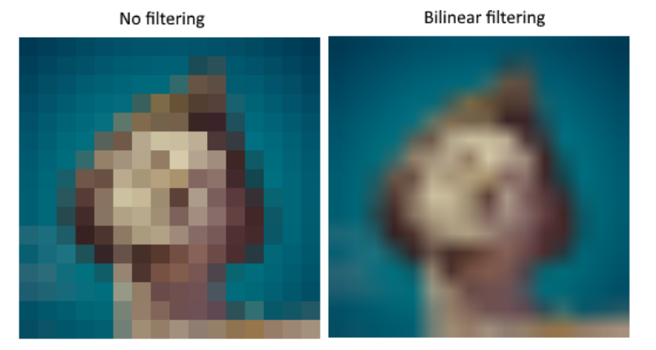
这些过滤器有助于处理过采样等问题。 考虑一个映射到几何图形的纹理,该纹理的碎片多于纹理像素。
如果只是在每个片段中使用最接近的纹理像素作为纹理坐标,那么将获得下图左边图像的结果:

而通过线性插值法将4个最接近的纹理像素组合在一起,那么将获得如上右图所示的更平滑的结果。 当然,您的应用程序可能具有更适合左侧风格的艺术风格要求(比如Minecraft,哈哈),但是在常规图形应用程序中,右侧风格是首选,图像越精细越好。 从纹理读取颜色时,采样器对象会自动为您应用此过滤。
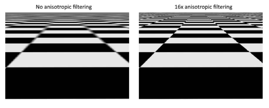
抽样不足(欠采样)则是相反的问题,比如纹理像素多于片段。这将导致在以锐角采样高频图案(如棋盘纹理)时产生伪影:

如左图所示,纹理在远处变得模糊混乱。解决这个问题的方法是各向异性滤波,它也可以由采样器自动应用。
除了这些过滤器,采样器还可以处理转换。它决定当你试图通过它的寻址模式读取图像外的texel时会发生什么。下面的图片显示了一些可能性:

2.1 createTextureSampler
现在创建一个函数createTextureSampler来设置这样的采样对象。稍后我们将在着色器中使用采样器从纹理中读取颜色:
1
2
3
4
5
6
7
8
9
10
11
12
13
14
15
16
17
18
19
20
21
22
23
24
25
26
27
28
29
30
31
32
33
34
35
36
37
38
39
40
41
42
43
44
45
46
47
48
49
50
51
52
53
54
55
56
57
58
59
60
61
| VkImageView textureImageView;
VkSampler textureSampler;
...
void initVulkan() {
...
createTextureImage();
createTextureImageView();
createTextureSampler();
...
}
void createTextureSampler() {
VkSamplerCreateInfo samplerInfo = {};
samplerInfo.sType = VK_STRUCTURE_TYPE_SAMPLER_CREATE_INFO;
samplerInfo.magFilter = VK_FILTER_LINEAR;
samplerInfo.minFilter = VK_FILTER_LINEAR;
samplerInfo.addressModeU = VK_SAMPLER_ADDRESS_MODE_REPEAT;
samplerInfo.addressModeV = VK_SAMPLER_ADDRESS_MODE_REPEAT;
samplerInfo.addressModeW = VK_SAMPLER_ADDRESS_MODE_REPEAT;
samplerInfo.anisotropyEnable = VK_TRUE;
samplerInfo.maxAnisotropy = 16;
samplerInfo.borderColor = VK_BORDER_COLOR_INT_OPAQUE_BLACK;
samplerInfo.unnormalizedCoordinates = VK_FALSE;
samplerInfo.compareEnable = VK_FALSE;
samplerInfo.compareOp = VK_COMPARE_OP_ALWAYS;
samplerInfo.mipmapMode = VK_SAMPLER_MIPMAP_MODE_LINEAR;
samplerInfo.mipLodBias = 0.0f;
samplerInfo.minLod = 0.0f;
samplerInfo.maxLod = 0.0f;
if (vkCreateSampler(device, &samplerInfo, nullptr, &textureSampler) != VK_SUCCESS) {
throw std::runtime_error("failed to create texture sampler!");
}
}
void cleanup() {
cleanupSwapChain();
vkDestroySampler(device, textureSampler, nullptr);
...
}
|
samplerInfo中的anisotropyEnable和maxAnisotropy这两个字段指定是否应该使用各向异性过滤。最大各向异性字段限制了可以用来计算最终颜色的texel样本的数量。数值越低,性能越好,但质量越低。目前没有任何图形硬件可以使用超过16个样本,因为超过这个值的差异就可以忽略不计了。
unnormalizedCoordinates字段指定要用于处理图像中纹理像素的坐标系。 如果此字段为VK_TRUE,则可以简单地使用[0,texWidth)和[0,texHeight)范围内的坐标。 如果为VK_FALSE,则将使用所有轴上的[0,1)范围对纹理像素进行寻址。 实际应用中几乎总是使用归一化的坐标,因为这样一来,便可以使用分辨率完全相同的不同分辨率的纹理。
请注意,采样器未在任何地方引用VkImage。 采样器是一个独特的对象,它提供了一个接口来从纹理中提取颜色。 它可以应用于所需的任何图像,无论是1D,2D还是3D。 这与许多较早的API不同,后者将纹理图像和过滤合并为一个状态。
2.2 VkSamplerCreateInfo
VkSamplerCreateInfo结构体指定了采样器对象的状态:
1
2
3
4
5
6
7
8
9
10
11
12
13
14
15
16
17
18
19
20
| typedef struct VkSamplerCreateInfo {
VkStructureType sType;
const void* pNext;
VkSamplerCreateFlags flags;
VkFilter magFilter;
VkFilter minFilter;
VkSamplerMipmapMode mipmapMode;
VkSamplerAddressMode addressModeU;
VkSamplerAddressMode addressModeV;
VkSamplerAddressMode addressModeW;
float mipLodBias;
VkBool32 anisotropyEnable;
float maxAnisotropy;
VkBool32 compareEnable;
VkCompareOp compareOp;
float minLod;
float maxLod;
VkBorderColor borderColor;
VkBool32 unnormalizedCoordinates;
} VkSamplerCreateInfo;
|
- sType是此结构的类型, VK_STRUCTURE_TYPE_SAMPLER_CREATE_INFO
- pNext是NULL或指向扩展特定结构的指针
- flag是VkSamplerCreateFlagBits的位掩码,描述了采样器的其他参数
- magFilter是VkFilter值,用于指定要应用于查找的放大滤镜
- VK_FILTER_NEAREST 指定最近的过滤
- VK_FILTER_LINEAR 指定线性过滤
- VK_FILTER_CUBIC_EXT 指定三次过滤
- VK_FILTER_CUBIC_IMG 指定三次过滤,同VK_FILTER_CUBIC_EXT
- minFilter是一个VkFilter值,用于指定要应用于查找的缩小过滤器
- mipmapMode是VkSamplerMipmapMode值,指定要应用于查找的mipmap过滤器
- addressModeU是VkSamplerAddressMode值,用于为U坐标指定[0..1]范围之外的寻址模式
- VK_SAMPLER_ADDRESS_MODE_REPEAT 当超出图像尺寸时,重复纹理
- VK_SAMPLER_ADDRESS_MODE_MIRRORED_REPEAT 类似于重复,但是当超出尺寸时会反转坐标以镜像图像
- VK_SAMPLER_ADDRESS_MODE_CLAMP_TO_EDGE 在图像尺寸之外,获取最靠近坐标的边缘的颜色
- VK_SAMPLER_ADDRESS_MODE_CLAMP_TO_BORDER 当采样超出图像尺寸时,返回纯色
- VK_SAMPLER_ADDRESS_MODE_MIRROR_CLAMP_TO_EDGE 类似CLAMP_TO_EDGE,但使用与最近边缘相反的边缘,仅在启用samplerMirrorClampToEdge或启用[VK_KHR_sampler_mirror_clamp_to_edge]扩展名后才有效
- addressModeV是VkSamplerAddressMode值,用于指定V坐标的[0..1]范围之外的寻址模式
- addressModeW是VkSamplerAddressMode值,它为W坐标指定[0..1]范围之外的寻址模式
- mipLodBias是要添加到mipmap LOD(详细程度)计算中的偏差,以及由SPIR-V中的图像采样功能提供的偏差
- anisotropyEnable为VK_TRUE以启用各向异性过滤,如“ Texel各向异性过滤”部分所述,否则为VK_FALSE
- maxAnisotropy是anisotropyEnable为VK_TRUE时采样器使用的各向异性值钳位。如果anisotropyEnable为VK_FALSE,则maxAnisotropy被忽略
- compareEnable为VK_TRUE,以允许在查找过程中与参考值进行比较,否则为VK_FALSE
- 注意:如果此成员不匹配,则某些实现将默认为着色器状态
- compareOp是一个VkCompareOp值,它指定比较功能,以按“深度比较操作”部分所述在过滤之前将其应用于获取的数据
- minLod和maxLod是用于钳位计算的LOD值的值
- borderColor是VkBorderColor值,用于指定要使用的预定义边框颜色
- unnormalizedCoordinates指定要用于处理图像中纹理像素的坐标系。设置为VK_TRUE时,用于查找纹理像素的图像坐标的范围在0到x,y和z的图像尺寸的范围内。设置为VK_FALSE时,图像坐标范围为零到一。
- 当unnormalizedCoordinates为VK_TRUE时,在着色器中使用采样器的图像具有以下要求:
- viewType必须为VK_IMAGE_VIEW_TYPE_1D或VK_IMAGE_VIEW_TYPE_2D
- 图像视图必须具有单个图层和单个mip级别
- 当unnormalizedCoordinates为VK_TRUE时,使用采样器的着色器中的图像内置函数具有以下要求:
- 这些功能不得使用投影
- 这些函数不得使用偏移量
2.3 vkCreateSampler
VkSampler对象表示图像采样器的状态,实现可使用该对象读取图像数据并为着色器应用过滤和其他转换。
1
2
3
4
5
| VkResult vkCreateSampler(
VkDevice device,
const VkSamplerCreateInfo* pCreateInfo,
const VkAllocationCallbacks* pAllocator,
VkSampler* pSampler);
|
- device是创建采样器的逻辑设备
- pCreateInfo是指向VkSamplerCreateInfo结构的指针,该结构指定采样器对象的状态
- pAllocator控制主机内存分配
- pSampler是指向VkSampler句柄的指针,在该句柄中返回生成的采样器对象
2.4 设备功能之各向异性过滤
如果现在运行程序,则会看到如下所示的验证层消息:

这是因为各向异性过滤实际上是一个可选的设备特性。我们需要更新createLogicalDevice函数来请求它:
1
2
| VkPhysicalDeviceFeatures deviceFeatures = {};
deviceFeatures.samplerAnisotropy = VK_TRUE;
|
即使现在的显卡不支持它的可能性很小,我们也应该更新isDeviceSuitable来检查它是否可用:
1
2
3
4
5
6
7
| bool isDeviceSuitable(VkPhysicalDevice device) {
...
VkPhysicalDeviceFeatures supportedFeatures;
vkGetPhysicalDeviceFeatures(device, &supportedFeatures);
return indices.isComplete() && extensionsSupported &&
swapChainAdequate && supportedFeatures.samplerAnisotropy;
}
|
vkGetPhysicalDeviceFeatures重新调整VkPhysicalDeviceFeatures结构的用途,通过设置布尔值来指示支持哪些功能,而不是请求哪些功能。
除了强制各向异性过滤的可用性,也可以通过条件设置不使用它:
1
2
| samplerInfo.anisotropyEnable = VK_FALSE;
samplerInfo.maxAnisotropy = 1;
|
2.5 小结
现在图像有了,接下来,我们将向着色器公开图像和采样器对象,以便将纹理绘制到正方形上并呈现出来。
三. 组合图像采样器
我们在统一缓冲区部分中了解了描述符。 现在我们看一种新型的描述符:组合图像采样器。 该描述符使着色器可以通过采样器对象访问图像资源。
我们将从修改描述符布局,描述符池和描述符集开始,以包括此类组合的图像采样器描述符。 之后,我们将向顶点添加纹理坐标,并修改片段着色器以从纹理读取颜色,而不仅仅是插入顶点颜色。
3.1 更新描述符
回到createDescriptorSetLayout函数,为组合的图像采样器描述符添加VkDescriptorSetLayoutBinding。 将其放在统一缓冲区之后的绑定中:
1
2
3
4
5
6
7
8
9
10
11
12
13
14
15
16
17
18
19
20
21
22
23
24
25
26
27
28
29
30
31
32
33
34
| void createDescriptorSetLayout() {
VkDescriptorSetLayoutBinding uboLayoutBinding = {};
uboLayoutBinding.binding = 0;
uboLayoutBinding.descriptorType = VK_DESCRIPTOR_TYPE_UNIFORM_BUFFER;
uboLayoutBinding.descriptorCount = 1;
uboLayoutBinding.stageFlags = VK_SHADER_STAGE_VERTEX_BIT;
uboLayoutBinding.pImmutableSamplers = nullptr;
VkDescriptorSetLayoutBinding samplerLayoutBinding = {};
samplerLayoutBinding.binding = 1;
samplerLayoutBinding.descriptorCount = 1;
samplerLayoutBinding.descriptorType = VK_DESCRIPTOR_TYPE_COMBINED_IMAGE_SAMPLER;
samplerLayoutBinding.pImmutableSamplers = nullptr;
samplerLayoutBinding.stageFlags = VK_SHADER_STAGE_FRAGMENT_BIT;
std::array<VkDescriptorSetLayoutBinding, 2> bindings = {uboLayoutBinding, samplerLayoutBinding};
VkDescriptorSetLayoutCreateInfo layoutInfo = {};
layoutInfo.sType = VK_STRUCTURE_TYPE_DESCRIPTOR_SET_LAYOUT_CREATE_INFO;
layoutInfo.bindingCount = static_cast<uint32_t>(bindings.size());
layoutInfo.pBindings = bindings.data();
if (vkCreateDescriptorSetLayout(device, &layoutInfo, nullptr, &descriptorSetLayout) != VK_SUCCESS) {
throw std::runtime_error("failed to create descriptor set layout!");
}
}
|
如果您现在运行带有验证层的应用程序,那么会发现描述符池无法使用此布局分配描述符集,因为它没有任何组合的图像采样器描述符。
转到createDescriptorPool函数并对其进行修改,以包括此描述符的VkDescriptorPoolSize:
1
2
3
4
5
6
7
8
9
10
11
12
13
14
15
16
17
18
19
20
21
22
23
24
25
26
| void createDescriptorPool() {
VkDescriptorPoolSize poolSize = {};
poolSize.type = VK_DESCRIPTOR_TYPE_UNIFORM_BUFFER;
poolSize.descriptorCount = static_cast<uint32_t>(swapChainImages.size());
std::array<VkDescriptorPoolSize, 2> poolSizes = {};
poolSizes[0].type = VK_DESCRIPTOR_TYPE_UNIFORM_BUFFER;
poolSizes[0].descriptorCount = static_cast<uint32_t>(swapChainImages.size());
poolSizes[1].type = VK_DESCRIPTOR_TYPE_COMBINED_IMAGE_SAMPLER;
poolSizes[1].descriptorCount = static_cast<uint32_t>(swapChainImages.size());
VkDescriptorPoolCreateInfo poolInfo = {};
poolInfo.sType = VK_STRUCTURE_TYPE_DESCRIPTOR_POOL_CREATE_INFO;
poolInfo.poolSizeCount = static_cast<uint32_t>(poolSizes.size());
poolInfo.pPoolSizes = poolSizes.data();
poolInfo.maxSets = static_cast<uint32_t>(swapChainImages.size());
if (vkCreateDescriptorPool(device, &poolInfo, nullptr, &descriptorPool) != VK_SUCCESS) {
throw std::runtime_error("failed to create descriptor pool!");
}
}
|
最后一步是将实际图像和采样器资源绑定到描述符集中的描述符。 转到createDescriptorSets函数:
1
2
3
4
5
6
7
8
9
10
11
12
13
14
15
16
17
18
19
20
21
22
23
24
25
26
27
28
29
30
31
32
33
34
35
36
37
38
39
| void createDescriptorSets() {
...
for (size_t i = 0; i < descriptorSets.size(); i++) {
...
VkDescriptorImageInfo imageInfo = {};
imageInfo.imageLayout = VK_IMAGE_LAYOUT_SHADER_READ_ONLY_OPTIMAL;
imageInfo.imageView = textureImageView;
imageInfo.sampler = textureSampler;
std::array<VkWriteDescriptorSet, 2> descriptorWrites = {};
descriptorWrites[0].sType = VK_STRUCTURE_TYPE_WRITE_DESCRIPTOR_SET;
descriptorWrites[0].dstSet = descriptorSets[i];
descriptorWrites[0].dstBinding = 0;
descriptorWrites[0].dstArrayElement = 0;
descriptorWrites[0].descriptorType = VK_DESCRIPTOR_TYPE_UNIFORM_BUFFER;
descriptorWrites[0].descriptorCount = 1;
descriptorWrites[0].pBufferInfo = &bufferInfo;
descriptorWrites[1].sType = VK_STRUCTURE_TYPE_WRITE_DESCRIPTOR_SET;
descriptorWrites[1].dstSet = descriptorSets[i];
descriptorWrites[1].dstBinding = 1;
descriptorWrites[1].dstArrayElement = 0;
descriptorWrites[1].descriptorType = VK_DESCRIPTOR_TYPE_COMBINED_IMAGE_SAMPLER;
descriptorWrites[1].descriptorCount = 1;
descriptorWrites[1].pImageInfo = &imageInfo;
vkUpdateDescriptorSets(device,
static_cast<uint32_t>(descriptorWrites.size()),
descriptorWrites.data(), 0, nullptr);
}
}
|
必须在VkDescriptorImageInfo结构中指定用于组合图像采样器结构的资源,就像在VkDescriptorBufferInfo结构中指定用于统一缓冲区描述符的缓冲区资源一样。
3.2 纹理坐标
纹理映射还有一个重要要素就是每个顶点的实际坐标。 坐标决定了图像如何实际映射到几何体:
1
2
3
4
5
6
7
8
9
10
11
12
13
14
15
16
17
18
19
20
21
22
23
24
25
26
27
28
29
30
31
32
33
34
35
36
| struct Vertex {
glm::vec2 pos;
glm::vec3 color;
glm::vec2 texCoord;
static VkVertexInputBindingDescription getBindingDescription() {
VkVertexInputBindingDescription bindingDescription = {};
bindingDescription.binding = 0;
bindingDescription.stride = sizeof(Vertex);
bindingDescription.inputRate = VK_VERTEX_INPUT_RATE_VERTEX;
return bindingDescription;
}
static std::array<VkVertexInputAttributeDescription, 3> getAttributeDescriptions() {
std::array<VkVertexInputAttributeDescription, 3> attributeDescriptions = {};
attributeDescriptions[0].binding = 0;
attributeDescriptions[0].location = 0;
attributeDescriptions[0].format = VK_FORMAT_R32G32_SFLOAT;
attributeDescriptions[0].offset = offsetof(Vertex, pos);
attributeDescriptions[1].binding = 0;
attributeDescriptions[1].location = 1;
attributeDescriptions[1].format = VK_FORMAT_R32G32B32_SFLOAT;
attributeDescriptions[1].offset = offsetof(Vertex, color);
attributeDescriptions[2].binding = 0;
attributeDescriptions[2].location = 2;
attributeDescriptions[2].format = VK_FORMAT_R32G32_SFLOAT;
attributeDescriptions[2].offset = offsetof(Vertex, texCoord);
return attributeDescriptions;
}
};
|
修改“顶点”结构,使其包含用于纹理坐标的vec2(texCoord)。 确保还添加了VkVertexInputAttributeDescription,以便我们可以将访问纹理坐标用作顶点着色器中的输入。 要将它们传递到片段着色器以便在正方形表面上进行插值,这是必要的。
1
2
3
4
5
6
| const std::vector<Vertex> vertices = {
{{-0.5f, -0.5f}, {1.0f, 0.0f, 0.0f}, {1.0f, 0.0f}},
{{0.5f, -0.5f}, {0.0f, 1.0f, 0.0f}, {0.0f, 0.0f}},
{{0.5f, 0.5f}, {0.0f, 0.0f, 1.0f}, {0.0f, 1.0f}},
{{-0.5f, 0.5f}, {1.0f, 1.0f, 1.0f}, {1.0f, 1.0f}}
};
|
先使用从左上角的0、0到右下角的1、1的坐标简单地用纹理填充正方形。 随意尝试使用不同的坐标。 稍后我们看看低于0或高于1的坐标下的实际的寻址模式!
3.3 着色器
最后一步是修改着色器,以从纹理中采样颜色。 我们首先需要修改顶点着色器,以将纹理坐标传递到片段着色器:
1
2
3
4
5
6
7
8
9
10
11
12
| layout(location = 0) in vec2 inPosition;
layout(location = 1) in vec3 inColor;
layout(location = 2) in vec2 inTexCoord;
layout(location = 0) out vec3 fragColor;
layout(location = 1) out vec2 fragTexCoord;
void main() {
gl_Position = ubo.proj * ubo.view * ubo.model * vec4(inPosition, 0.0, 1.0);
fragColor = inColor;
fragTexCoord = inTexCoord;
}
|
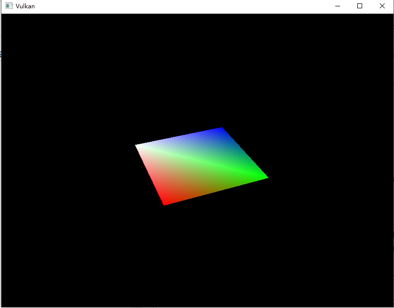
就像每个顶点的颜色一样,栅格化器会将fragTexCoord值平滑地插入到正方形区域中。 我们可以通过使片段着色器将纹理坐标输出为颜色来形象化:
1
2
3
4
5
6
7
8
9
10
11
| #version 450
#extension GL_ARB_separate_shader_objects : enable
layout(location = 0) in vec3 fragColor;
layout(location = 1) in vec2 fragTexCoord;
layout(location = 0) out vec4 outColor;
void main() {
outColor = vec4(fragTexCoord, 0.0, 1.0);
}
|
现在我们编译下着色器,然后运行下程序:

3.3.1 片段着色器中的图像采样器描述符
组合的图像采样器描述符在GLSL中由采样器统一表示。 在片段着色器中添加对它的引用:
1
2
3
4
5
6
| # 对于其他类型的图像,存在等效的sampler1D和sampler3D类型。 确保在此处使用正确的绑定。
layout(binding = 1) uniform sampler2D texSampler;
void main() {
outColor = texture(texSampler, fragTexCoord);
}
|
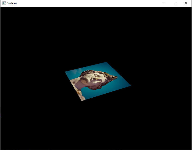
编译一下shader然后运行程序:

哒哒,一个旋转的贴图出现了!


